The MSRP moved from a two-fluid breeder reactor design to a one-fluid design early in 1968 due to the convergence of several developments.
The design studies on the two-fluid reactor had reached a reasonable stopping point in September 1967, and a design power for the MSBE had been selected as 150 MW thermal. In order to improve the performance of the two-fluid reactor, reductive extraction of protactinium from the blanket into bismuth had been investigated. There was hope that protactinium extraction would allow operation of the reactor at a higher core power density while still achieving a high breeding ratio (on the order of 1.08). There had also been investigations into the reductive extraction of lanthanide fission products from the fuel salt into bismuth. The initial results appeared to be promising. A one-fluid breeder would need protactinium to be rapidly and efficiently removed, allowing it to decay to uranium-233 outside of the destructive neutron flux of the reactor. A one-fluid breeder would also have a stronger need than a two-fluid reactor for the rapid removal of lanthanide fission products. Developments in bismuth extraction appeared to provide optimism that such a design change could be accommodated.
One-fluid reactors were also neutronically “leaky” in comparison to two-fluid reactors. There was no absorptive blanket region to productively capture neutrons before they could escape from the reactor vessel. But designers believed they could recreate much of the effect of the blanket in a one-fluid reactor by reducing the moderation (by changing the salt to graphite ratio) and improving the potential of the fertile content of the salt (thorium) to absorb neutrons. By creating two different regions with the positive displacement material (graphite) they could approximate two purposes with a single fluid. It was imperfect, but it seemed to be a positive step.
The drive for the one-fluid design was the challenge of replacing prismatic graphite structures in the design described in ORNL-4191. Due to the complexity of the connections between the graphite fuel cells and the entrance and exit plena, the most acceptable way that they had conceived for graphite replacement was a replacement of the entire core vessel and all the graphite and metallic structures inside it. If the replacement frequency was driven only by the radiation-induced dimensional changes in the graphite this did not appear to be uneconomical. What concerned them was that mechanical failures of individual graphite cells would lead to a replacement frequency for the entire core that was excessive and expensive.
In the one-fluid design, the prismatic graphite structures served only as a moderator and a definition for flow channels; they had no structural function as they did in the two-fluid design. The entrance and exit plena to the core could be simply defined by the placement of graphite prisms. There was no need for a specific plenum structure because there were no fluids to separate. Graphite replacement could be much easier if prisms could be removed individually or in groups without the need to cut them from a plenum or attempt to reconnect them.
None of these realizations was fundamentally incorrect. But there was a degree of over-optimism about the potential performance of the chemical processing system, coupled with an under-appreciation of the loss in versatility, performance, and safety that would be lost with the abandonment of the two-fluid design, that led MSRP designers and engineers to embrace the one-fluid concept.
ORNL-4254, September 1967-February 1968
The first concept for a one-fluid breeder reactor was described in the February 1968 semiannual progress report (ORNL-4254). This design differed in many ways from the previous two-fluid design described in ORNL-4191. The first difference was that it was huge. Rather than a small 250-MWe core design, it was a 2000-MWe (4444 MWt) core that was 18 feet in diameter. Core power density was increased from 20 kW/liter in the ORNL-4191 design back to the 40 kW/liter value that earlier designs had used. Core volume was 4020 ft3, approximately eight times greater than the ORNL-4119 design that had also been designed with a 40 kW/liter average core power density. It was as if designers were attempting to fit eight of their previous reactors in a single vessel in the new design. The core elevation is shown in Figure 1.
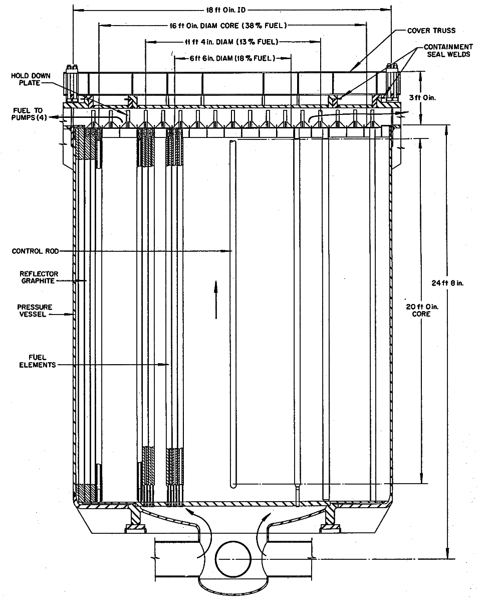
The fuel salt, now serving a dual purpose, contained both thorium and uranium tetrafluorides in solution. Its composition was LiF-BeF2-ThF4-UF4 (67.7-20-12-0.3 mole%). The coolant salt continued to be a mixture of sodium fluoroborate and sodium fluoride (92-8 mole%). Graphite was the moderator material and Hastelloy-N the metallic alloy.
With the change in fuel composition came a change in fuel inlet and outlet temperatures. The outlet temperature remained 1300°F, reflecting the material limitation of the Hastelloy-N, but the inlet temperature was raised to 1050°F due to the higher liquidus temperature of the heavier fuel salt. The fuel salt used in the two-fluid design had been a relatively light mixture of primarily LiF-BeF2, with a small amount of UF4 dissolved in it. But the fuel salt of the one-fluid, which included substantial amounts of ThF4 in it, was heavier and required more pumping power.
The reflector was 12 inches in thickness, an increase from previous concepts that could rely on the fertile blanket to productively capture neutrons before they reached the vessel wall. A thick graphite reflector would be a general feature of the one-fluid breeder designs, because of the importance of minimizing neutron loss from the vessel. There were 1760 individual graphite elements in the core.
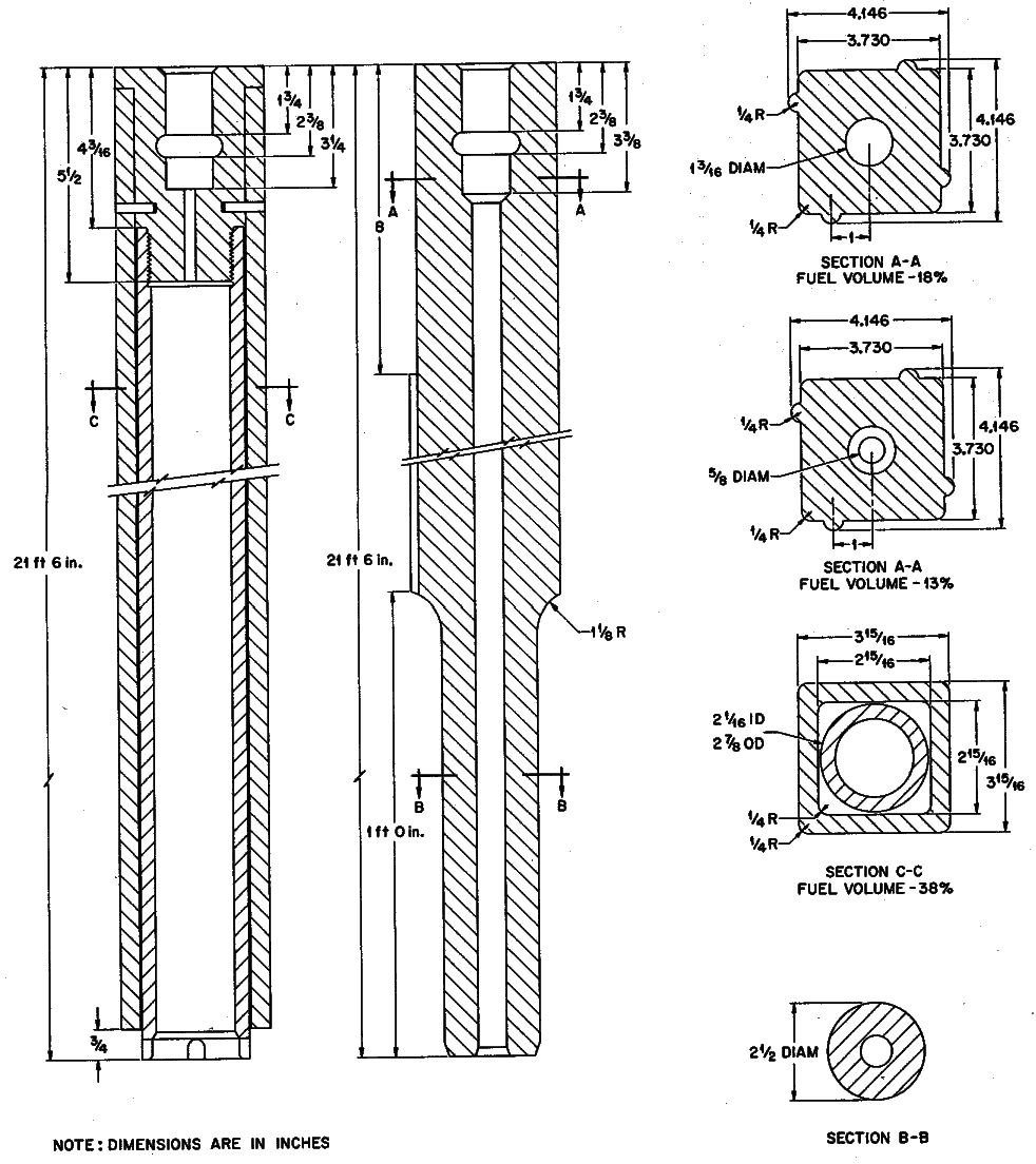
The flow pattern also changed with the transition from two-fluid to one-fluid. The salt entered at the bottom of the reactor and flowed along the interior and exterior of square graphite prisms with a single channel bored down the center, as shown in Figure 2. Raised “knobs” on the exterior of the prism, running the length of the structure, provided clearance between prisms and created flow channels on the exterior surface of the prism. Another type of prismatic structure was formed from a hollow box inset with a hollow cylinder. This generated a different salt-to-graphite volume ratio and was used in the periphery of the reactor core to create an undermoderated region where neutron absorption would be enhanced. These two different types of graphite structures were needed to create the “core” and “blanket” approximation in a large one-fluid reactor.
The breeding ratio of the new design was uncertain, and was listed as a range of 1.03 to 1.08. Other fuel processing performance aspects of the new design were not given, reflecting the short amount of time the design team had had to make such a significant change.
ORNL-4344, March 1968-August 1968
The August 1968 progress report brough the one-fluid design into greater focus and began to appear more like the “reference” configuration that would ultimately be realized in the next report.
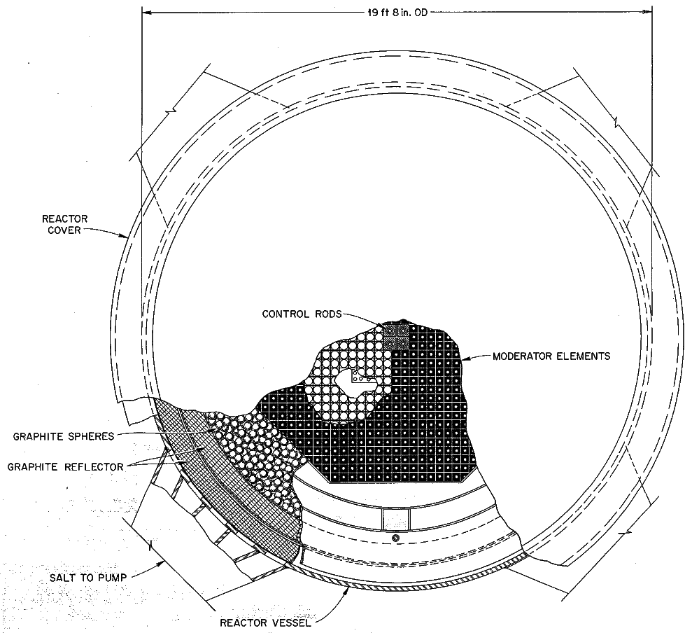
In cross-section, the core region of fuel cells had the shape of an octagon, as shown in Figure 3. An 18-inch-thick graphite reflector lined the interior of the metallic reactor vessel. The concept of a transition region using graphite spheres made a return in this design, filling the gap between the octagonal core and the annular reflector. Average core power density was again reduced to 29 kW/liter and the design thermal power was reduced to 2250 MW for an electrical output of 1000 MWe. Despite the reduction in design power, the reduction in core power density led to larger overall core diameter of 236 inches. The core was squat, without axial graphite blankets to prevent leakage in that direction, as shown in Figure 4.

Protactinium was removed aggressively, on a 3-day cycle, while fission products were removed on a 50-day cycle. Breeding ratio was calculated at 1.077, nearly as good as a two-fluid design.
ORNL-4396, September 1968-February 1969
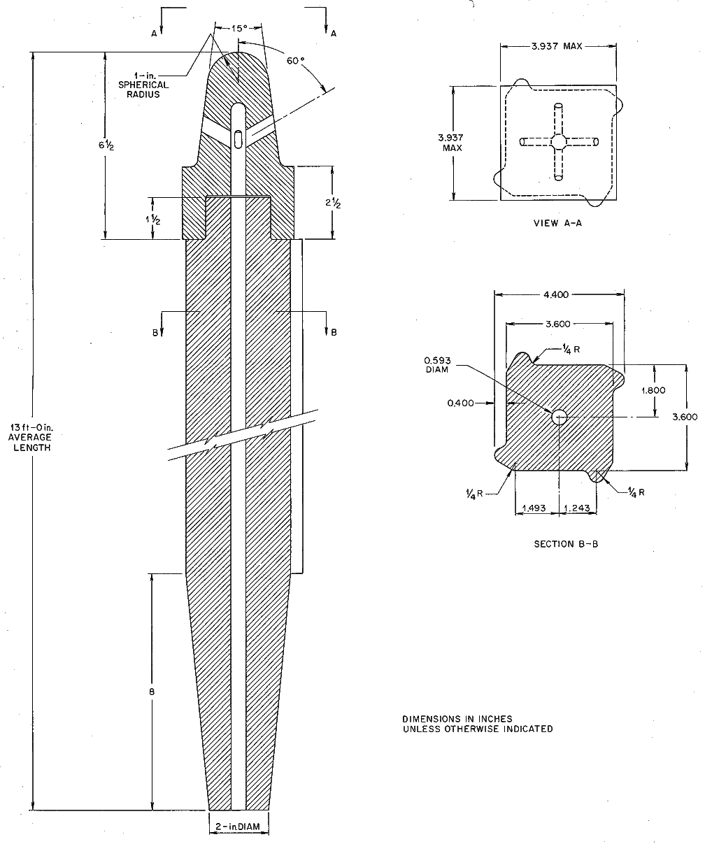
By the time the semiannual report ending February 1969 was published, the design of the core had very nearly reached its final configuration. As shown in Figure 6, the core prismatic elements now all had a single uniform length, but they were bounded on either end by a thick axial reflector. The radial reflector was also very thick at 30 inches.

The cross-section of the core vessel, shown in Figure 7, showed that the fuel cells retained their overall octagonal design. The radial reflector was divided into wedges that were stacked one on another as blocks to form the reflector structure. The transition from the prismatic core to the annular reflector was achieved by a series of radial graphite ribs or salts that were of variable length. The entire vessel was filled with fuel salt, but flow patterns varied in order to accomplish different goals, such as the keeping of the vessel wall and reflector cooler than the interior of the reactor.

The core power density was reduced to 22.2 kW/liter and the reactor vessel was 270 inches in diameter, with 1412 graphite elements therein set on a 4-inch pitch.
Fuel was processed for protactinium on a 3-day cycle and fission products on a 30-day cycle. Breeding ratio was anticipated to be 1.06.

ORNL-4541, MSBR Conceptual Design Study, June 1971
The “reference” one-fluid reactor design was written up in a separate report, ORNL-4541, published in June 1971. The reactor design described therein was nearly identical to the one revealed in ORNL-4396. One of the only changes was a modification to the fuel processing schedule, with ORNL-4541 projecting a protactinium and fission-product removal time of 10 days.
ORNL-4548, September 1969-February 1970
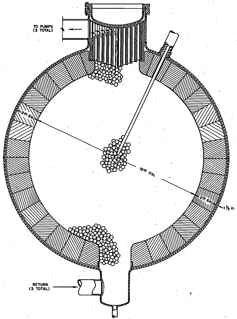
Later an attempt to simplify the entire core design was briefly considered in ORNL-4548. As shown in Figure 9, the core vessel would be made spherical and lined with thick graphite wedges to act as the reflector. The interior volume would be filled with graphite spheres and fuel salt. The advantage of this design was that the addition and removal of graphite spheres was considered simple. The fatal disadvantage of the design, however, was that the necessary volume ratio between the fuel salt and the graphite could not be achieved with loose graphite spheres, and so the idea was not pursued further.
One-Fluid MSBR Core Design Summary
Four of the one-fluid reactor designs are compared in Table 1. They show that most design aspects remained fairly stable in the evolution of one-fluid designs, with the exception of the steady reduction in core power density. Notable is the steady increase in graphite reflector thickness that accompanied between understanding of the neutronics of one-fluid breeder designs.
Table 1: Comparison of One-Fluid Breeder Reactor Designs
![\begin{table}[htp] \footnotesize \centering \begin{tabular}{lp{2.5cm}p{2.5cm}p{2.5cm}p{2.5cm}} \midrule & ORNL-4254 & ORNL-4344 & ORNL-4396 & ORNL-4541\\ & February 1968 & August 1968 & February 1969 & June 1971\\ \midrule Materials\\ \hspace{0.25cm}Fuel salt & \multicolumn{4}{l}{LiF-BeF$_2$-ThF$_4$-UF$_4$}\\ \hspace{0.25cm}Composition, mole\% & 67.7-20-12-0.3 & 71.7-16-12-0.3\\ \hspace{0.25cm}Coolant fluid & \multicolumn{4}{l}{NaBF$_4$-NaF}\\ \hspace{0.25cm}Composition, mole\% & 92-8\\ \hspace{0.25cm}Moderator & graphite\\ \hspace{0.25cm}Structural alloy & Hastelloy-N\\ \\ Reactor vessel\\ \hspace{0.25cm}Design thermal power, MW & 4444 & 2250 & 2250 & 2250\\ \hspace{0.25cm}Average power density, kW/L & 40 & 29 & 22.2 & 22.2\\ \hspace{0.25cm}Outer diameter, in & 219.3 & 236 & 270 & 270\\ \hspace{0.25cm}Vessel height, in & 294 & 192 & 240 & 240\\ \hspace{0.25cm}Prismatic arrangement & square & square & square & square\\ \hspace{0.25cm}Prismatic pitch, in & 3-15/16 & 3-15/16 & 4 & 4 \\ \hspace{0.25cm}Number of core elements & 1760 & 900 & 1412 & 1412\\ \hspace{0.25cm}Fuel cell X-S geometry & square & square & square & square\\ \hspace{0.25cm}Transition region & not described & graphite spheres & radial slats & radial slats\\ \hspace{0.25cm}Reflector thickness, in & 12 & 18 & 30 & 30\\ \\ Temperatures, $^\circ$F\\ \hspace{0.25cm}Fuel inlet/outlet & 1050/1300 & 1050/1300 & 1000/1300 & 1000/1300\\ \hspace{0.25cm}Coolant inlet/outlet & 850/1150 & 850/1150 & 850/1150 & 850/1150\\ \\ Processsing\\ \hspace{0.25cm}Total fuel volume, ft$^3$ & 2445 & not specified & 1720 & 1720\\ \hspace{0.25cm}Fuel processing rate, days & 38 & 50 & 30 & 10\\ \hspace{0.25cm}Pa processing rate, days & 3 & 3 & 3 & 10\\ \hspace{0.25cm}Fissile inventory, kg & 1880 & 1600 & 1470 & 1504\\ \hspace{0.25cm}Fertile inventory, kg & 90,000 & not specified & 68,000 & 68,100\\ \hspace{0.25cm}Specific power, MWt/kg & 2.36 & 1.4 & 1.53 & 1.50\\ \hspace{0.25cm}Specific inventory, kg/MWe & 0.94 & 1.6 & 1.47 & 1.50\\ \hspace{0.25cm}Breeding ratio & 1.048 & 1.077 & 1.06 & 1.06\\ \\ Net thermal efficiency & 45\% & 44.4\% & 44.4\% & 44.4\%\\ Reactor electrical power, MW & 2000 & 1000 & 1000 & 1000\\ \midrule \end{tabular} \end{table}](https://energyfromthorium.com/wp-content/ql-cache/quicklatex.com-13beb905adb53ab68f5af30e788bed54_l3.png "Rendered by QuickLaTeX.com")
- ORNL-4254 performance data largely from Table 5.2, pg 59.
- ORNL-4344 performance data largely from Table 5.1, pg 56.
- ORNL-4396 performance data largely from Table 5.1, pg 54.
- ORNL-4541 performance data largely from Table S.1, pgs xi-xv.