The earliest designs for thermal-spectrum molten-salt breeder reactors using thorium were conceived before graphite was known to be a suitable moderator material. They primarily relied on the moderating properties of the salt itself, which were poorer than graphite. Because of this limitation they could not achieve a truly thermal-neutron spectrum and this led to higher fuel inventories. The absorption of neutrons in the salt constituents (lithium, beryllium, and fluorine) is rather low, but not nearly so low as graphite, so there were larger neutronic losses to the salt itself.
The barrier material between the core and blanket salts was metallic and this structure would have a limited lifetime, if it even was feasible.
In-pile experiments with graphite in the early 1960s established its chemical and neutronic stability with the fuel and blanket salts, allowing graphite-moderated reactors to begin to be considered in future designs. The first fruit of this realization was the decision to manufacture unclad graphite moderator elements for the Molten-Salt Reactor Experiment, which had been approved for construction in 1960.
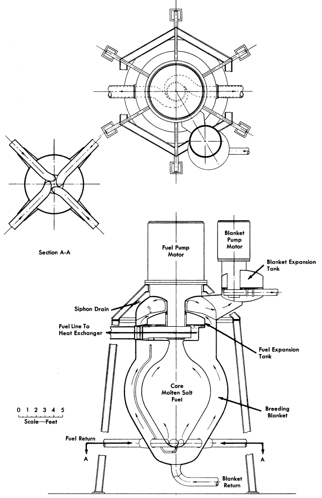
ORNL-3708, February 1964-July 1964
In a 1964 progress report (ORNL-3708), the researchers of the MSRP put forward a concept for a thorium breeder reactor that first used a prismatic core design, where the prismatic structures consisted of graphite extrusions. Their primary motivation for attempting the challenging goal of the breeder was the unforgiving nature of resource calculations for reactors that fell much short of breeding.
Realization of a system that makes full use of the potential energy in thorium to produce cheap electricity is the primary mission of reactor development at the Oak Ridge National Laboratory. That system must be an efficient breeder system. An advanced converter may be a worthwhile step in the development, but an advanced converter does not reach the goal. No matter how good the conversion ratio, if it is significantly less than 1, the amount of uranium that must be mined to make up the deficit in fissionable material is greater than the amount of thorium that must be mined to compensate for the thorium converted to 233U and burned. For example, if the conversion ratio is 0.90, the 235U from 20 tons of natural uranium will be burned with each ton of thorium consumed. Even with a conversion ratio of 0.99, the 235U from 2 tons of uranium must be supplied with each ton of thorium.
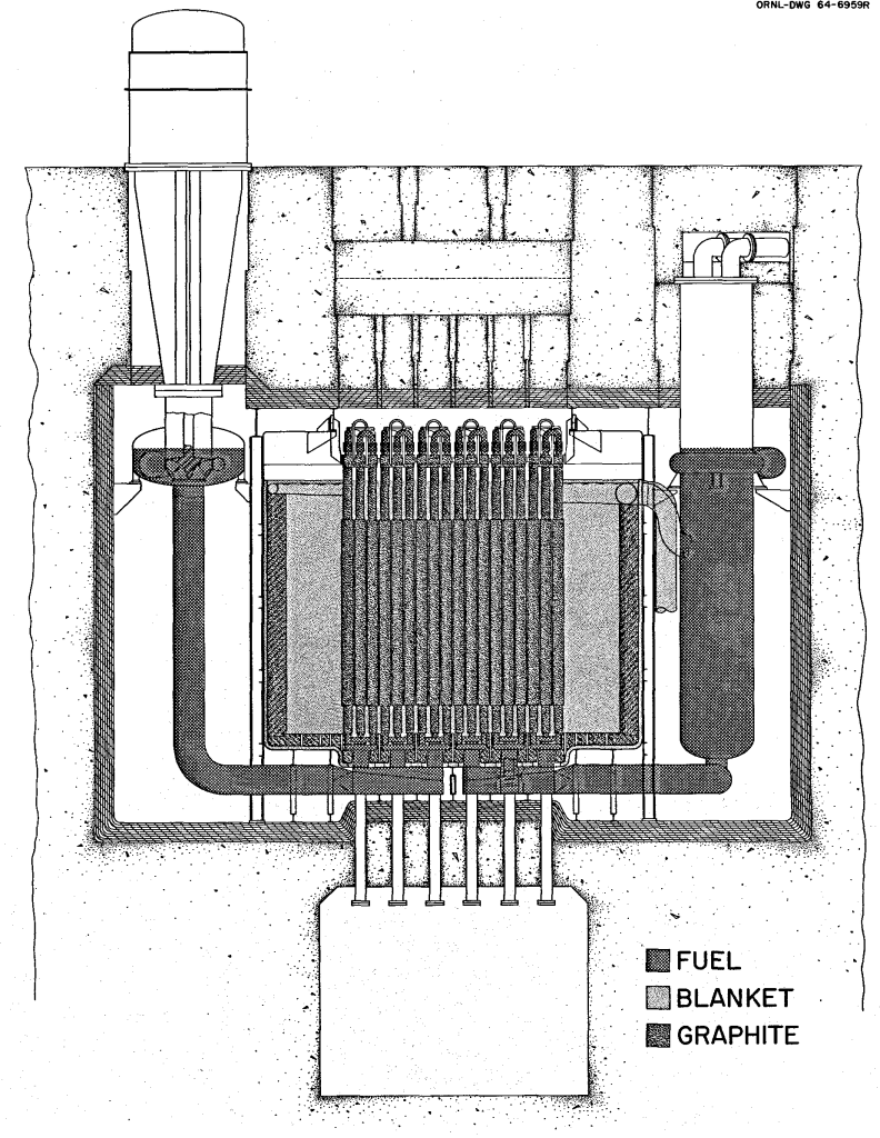
Their concept for the breeder reactor, shown in Figure 2, used the graphite prisms as the flow channels for the fuel salt. Each graphite prisms had a square cross-section at the bottom and top of the structure, which was shaped into a circular cross-section in the “core” region between the ends. A central circular channel was bored into each graphite prism. Blanket salt was allowed to flow into interstitial regions between the graphite blocks. At the top and bottom of each set of graphite blocks, flexible piping redirected the upcoming flow from one block into the downgoing flow into an adjacent block. The graphite blocks were arranged on a square pitch (distance between centers) of 8 inches. The complication of that arrangement can be seen in Figure 3.

The overall average core power density was 40 kW/liter and the core consisted of 324 prismatic elements. Fuel salt entered the reactor at 1125°F and left at 1300°F, for a ΔT across the reactor of 175°F. The proposed coolant was a fluoride salt mixture (LiF-NaF-KF) that would enter the primary heat exchanger at 950°F and exit at 1100°F. This led to an anticipated thermal efficiency of 42-45%. The design power of the reactor was 1000 MWe from a core power of 2400 MWt.
The reactor vessel was to be constructed of a modified Hastelloy-N alloy and would be 240 inches in outer diameter. A graphite reflector 12 inches thick lined the interior of the reactor vessel. No special structure was described to achieve a transition from the prismatic structure of the core to the annular structure of the reflector and core vessel. There was simply a gap between the prismatic core and the reflector that would be filled by blanket fluid, as can be seen in Figure 2.
This design proposed to process the reactor’s fuel inventory in 10-60 days and the blanket inventory every 35-200 days. The anticipated breeding ratio was 1.08, but this had not been rigorously verified. Based on a fissile inventory of 880-1220 kg, the reactor achieved a specific fissile inventory of 0.88 to 1.22 kg of fissile for each electrical megawatt generated.
ORNL-3936, September 1965-February 1966
Studies of a thorium breeder reactor began in earnest in September 1965, following the successful completion and startup of the Molten-Salt Reactor Experiment. In the MSRP semiannual report of February 1966 (ORNL-3936), a new reactor core design was put forward that showed a number of design innovations. The reactor was sized for 1000 MWe from 2220 MWt, assuming a nearly 45% efficient steam turbine power conversion system and subtracting for station loads. The average core power density had been doubled to 80 kW/liter as well, which led to a more compact reactor vessel 120 inches in outer diameter and 150 inches high, shown in Figure 4.
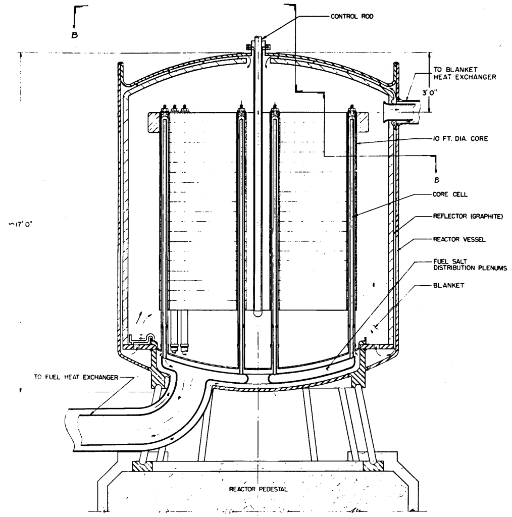
The reactor core was also prismatic, but now the up-and-down flow of fuel salt through the core would be confined to a single “fuel” cell rather than passing from one channel to another, as shown in Figure 5. The graphite prisms were hexagonal in cross-section rather than square and set on a triangular pitch of 4.8 inches, with 534 in total. Salt flowed upward through the prism through eight small circular channels, and then was turned at the top of the prism by a plug structure and flowed downward through a central circular bore. This strategy eliminated the external plumbing of the ORNL-3708 core module design, internalizing the flow into a single graphite prism. Blanket salt filled the interstices between the prismatic structures, and the nominal core composition was 75% graphite, 18% fuel salt, and 7% blanket salt by volume.

The prismatic core structure was set into the reactor vessel mounted to the top of a plenum structure. Inside the plenum structure the exit plenum was fully enclosed in the entrance plenum. Each “fuel cell” was connected to each plenum by graphite-to-metal transition sleeves. The fuel cells were only anchored at one end to permit axial movement due to thermal expansion. There was no transition region between the prismatic core and the annular 3-inch graphite reflector immediately inside the reactor vessel. This can be seen in Figures 4 and 6.

Fuel salt entered the reactor at 1000°F and left at 1300°F, for a ΔT of 300°F. A mixture of sodium fluoroborate and sodium fluoride (39-61 mole%) was proposed that would enter the primary heat exchanger at 850°F and exit at 1125°F. The blanket salt was held to a smaller temperature range, entering the reactor at 1150°F and leaving at 1250°F (ΔT = 100°F).
Fuel would be processed every 47 days and blanket every 23 days. The total fuel volume in the primary circuit and processing system was 717 ft3 and the total blanket volume was 3383 ft3. With the high core power density this design projected a fissile inventory of only 769 kg, leading to a specific fissile inventory of 0.77 kg/MWe. The high core power density diminished the breeding ratio to 1.049, most likely due to neutron loss to protactinium. The fertile inventory of 260,000 kg of thorium was over 300 times greater than the fissile.
ORNL-4119, September 1966-February 1967
The next semiannual report in August 1966 (ORNL-4037) proposed a substantial change to the design approach, employing four 250-MWe modules rather than a single 1000-MWe reactor. There was also discussion of how the removal of protactinium in the blanket (rather than waiting for the protactinium to decay to uranium) would improve overall performance.
The February 1967 semiannual report (ORNL-4119) adopted the modular 250-MWe reactors (each with 556 MW of thermal power) as the baseline approach. The average power density of the core was reduced to 40 kW/liter. The graphite “fuel cell” that made up the primary structure of the core was modified from a hexagonal cross-section to a circular cross-section, such that the fuel cell was essentially a long graphite cylinder. The fuel cells were enlarged to 5 inches in diameter and their number reduced to 336. In their center was a circular bore 1.5 inches in diameter, surrounded by three 7/8-in diameter holes for the upward flow from the entrance plenum, as shown in Figure 7.

Temperature ranges for fuel, blanket, and coolant were all retained from the previous design. The plenum structures evolved but remained similar in concept, with a central feed and drain rather than an offset design. A transition structure was first proposed in this design, employing graphite spheres 4 inches in diameter to fill the region between the prismatic core and the annular graphite reflector. Each graphite ball had holes in them so that blanket salt occupied 60% of the volume of the transition region. The reflector’s thickness was increased to 6 inches. These changes can be seen in Figure 8.
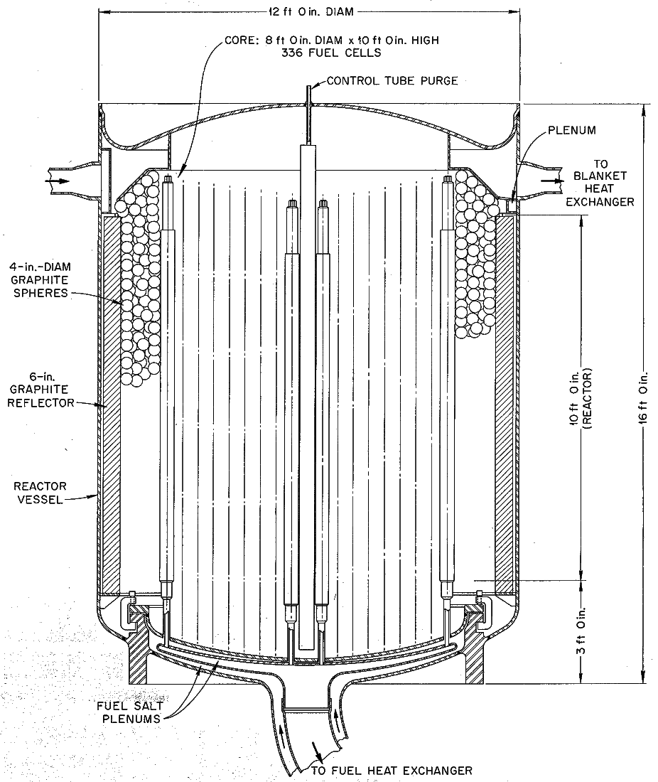
Fuel and blanket processing times remained largely the same but breeding ratio improved to 1.07 due to the lower core power density of the design.
A control rod was envisioned for the central position in the core. The control rod would not be a rod in the conventional sense, but there would be a hollow graphite cylinder 5 inches in diameter, the same as the other fuel cells, and equipped with a gas inlet at the top. The hollow graphite cylinder would naturally fill with blanket salt, which was a neutron absorber and would be particularly effective in this central region of the reactor. Gas pressure would be used to position the height of the blanket salt column at any position desired within this cell, and this column height would be used for control of the reactor. If the gas were expelled, the column would fill with blanket salt, introducing negative reactivity and tending towards reactor shutdown.
An alternative approach would be to position a graphite rod 5 inches or less in diameter in this central position and to actuate it from above. By pushing the rod down into the blanket, positive reactivity would be introduced, and by withdrawing the rod and allowing the volume to fill with blanket fluid, negative reactivity would be introduced. Since the blanket salt was more dense than graphite, a loss of actuation capability would cause the graphite rod to float upward in the reactor, ideally leading to a reduction in reactivity.
ORNL-4191, March 1967-August 1967
The next semiannual report from August 1967 (ORNL-4191) was the last to feature the two-fluid design. Because design work shifted to the one-fluid core design, the two-fluid design described in ORNL-4191 became the “reference” two-fluid design, and was written up in greater detail in the final report on two-fluid reactor design efforts, ORNL-4528, Two-Fluid Molten-Salt Breeder Reactor Design Study, published in August 1970.
The “reference” two-fluid design described in ORNL-4191 and ORNL-4528 reduced the core power density further, from 40 kW/liter to 20 kW/liter, in order to improve graphite lifetime in the core. There were also significant changes to the graphite “fuel cells”. The geometry was again changed back to a hexagonal cross-section, with an inner diameter (flat-to-flat distance) of 5.375 inches. A single circular channel 2-23/32 inches in diameter was to be bored down the centerline of each graphite prism. Inside that channel would be another cylindrical channel of graphite 3/4-inch in thickness and 2-1/4 in diameter. Salt would flow upward on the outside of this “recursive” channel and then flow downward on the inside, as shown in Figure 9. With this technique, the need to drill multiple passages down the length of graphite fuel cells was done away with, and this could lead to a substantial improvement in manufacturability. The concentric flow channels were generated by placing the inner cylindrical graphite structure in the bore of the larger hexagonal graphite prism. This simple approach to a “recursive” fuel channel has been mimicked in our newer designs.
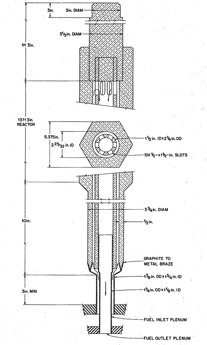
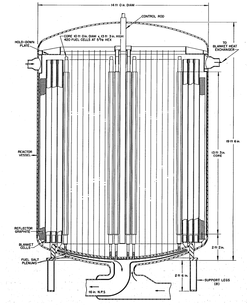
The prismatic pattern of core structures continued across the entire cross section of the core, but comprised three distinct regions. The three regions can be seen in the core cutaway view shown in Figure 12. The central region of the reactor was composed of the hexagonal “fuel cells”, in which the fuel salt flowed upward through a central bore and then downward through a concentric graphite sleeve inside the bore. There were to be 420 of these structures in the reactor vessel. Blanket salts fills the interstitial space between graphite fuel cells. Surrounding the “core” of hexagonal graphite prisms is a “blanket” constructed of simple graphite cylinders, open at both ends, providing for the flow of blanket salt and whose geometry achieves the desired graphite-to-salt volume ratio in the blanket. There were to be 252 of these graphite cylinders, including one in the central location of the reactor that would act as a position for a control rod. The outermost region is the “reflector” consisting of solid graphite cylinders. Some of these cylinders were to be trimmed in order to fit them into the core. This trimming apparently constituted the transition between the prismatic pattern and the metallic reactor vessel.


The manner in which the graphite fuel cells were to be attached to the entrance and exit plena constituted a challenge to the design. The outer graphite structure was to be brazed to a metallic section at the bottom end, and this metallic section would then be welded into the fuel entrance plenum. The inner, “recursive” graphite channel would be fitted to another metallic section using a sliding fit, and then the metallic section would be welded to the exit plenum. Leak-tightness between the exit stream and the entrance stream was not crucial since both streams were of the same composition, differing only in temperature.
The challenge of the design came about in the event that one of the fuel cells needed to be replaced. With the hexagonal geometry of the fuel cells and the very small interstitial space for blanket salt flow between them, there was no room for a long-handled tool to be inserted from the top of the reactor down to the area where the fuel cells connected to the entrance and exit plena. The only option would be to remove the central channel (a simple graphite annular cylinder) and to remove fuel cells, one after another, until the area was reached where the defective fuel cell was present. This would likely involve removing many good fuel cells in order to replace a single defective one. Returning, repairing, and rewelding each of these fuel cells remotely was also a very conceptually challenging task. Each fuel cell would require two welds.

The salt flow patterns in the entrance and exit plena were also never described in detail, but their facile design leads one to consider that they may have embodied many challenges. Since the distance from the large entrance channel to the individual small entrance channels of each fuel cell is different, the pressure drop that could be expected would be highly variable, favoring the fuel cells nearer to the entrance and exit at the expense of those furthest away. It would be desirable to shape the flow through the plena in a way to create uniform pressure drop across each fuel cell, but there is no indication that this was attempted in any of the ORNL two-fluid designs.
The severe challenge of replacing defective fuel cells led ORNL designers to consider instead the replacement of the entire reactor core vessel, with all its graphite internal structures, rather than to have to face the challenge of the individual replacement of defective fuel cells. But this led to great uncertainty. What would be the replacement frequency of defective fuel cells? They had assessed the core replacement frequency due to graphite dimensional change under fast neutron flux and not found it economically excessive, but the uncertainty associated with defective fuel cell replacement was deemed unacceptable. This was the central reason that consideration of one-fluid core designs began.
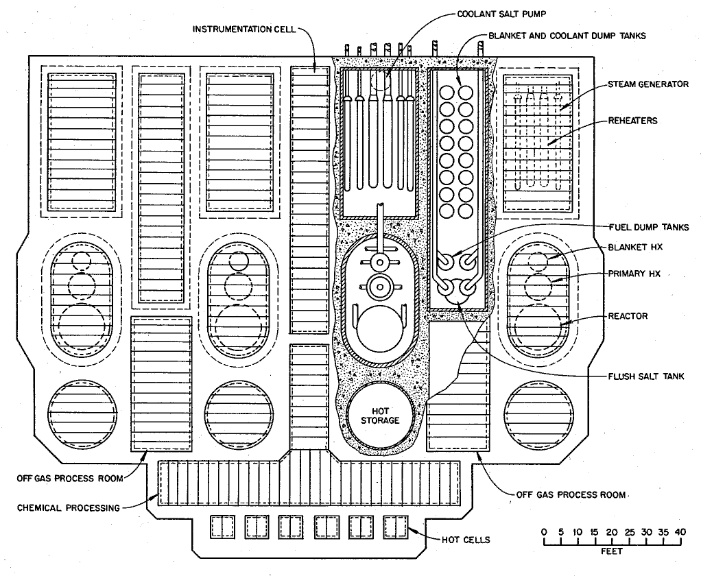
The importance of removing a defective reactor core influenced the design of the entire reactor module construction. A separate spent reactor vessel cell, labeled “Hot Storage” was included as a place for the spent reactor vessel to cool down after removal and before disassembly, shown in Figure 13. Considerations of disassembly were not included in the final report on the two-fluid design.
Four of the two-fluid reactor designs are compared in Table 1. They show the evolution in core power density from one design to another. One can also observe the changes in transition zone concepts as that issue came into focus. Changes in breeding ratio also accompanied changes in core power density. Later improvements in chemical removal techniques for protactinium would help decouple those effects from one another.
Table 1: Comparison of Two-Fluid Breeder Reactor Designs
![]()
- ORNL-3708 salt composition data from Table 1, pg 4.
- ORNL-3936 performance data largely from Table 6.1, pgs 180-181 and Table 6.7, pg 188, also from ORNL-3996, Table 3.1, pgs 37-38 and Table 3.1, pg 41.
- ORNL-4119 performance data largely from Table 9.1, pg 176.
- ORNL-4191 performance data largely from Table 5.2, pg 75.
- Some values for the ORNL-4191 design were taken from the later summary report ORNL-4528.

table 1 – comparison of 2 fluid designs is unreadable. html error maybe.
guys something wrong on this page, i can see HTML instead of the comparison table